
B9X Electronics Radio Interface Module
Introduction
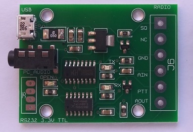
Our radio interface module provides a method to interface your computer to a radio. It facilitates microphone and speaker audio via a standard 3.5 mm 4 pole jack. Control is achieved via its and USB female connector.
When purchasing, a download link is provided that has a Windows DLL and Xojo Desktop example project. This project shows how to transmit, read the squelch line, and speak using text to speech. In this project, you simply set the COM port that this module is using. This can be determined in the Windows Device Manager by pluging/unpluging the USB connection. You just view the changes in the Device Manager.
The module features a Micro B snug-fitting USB connector to prevent accidental disconnects from your PC. It furthermore features control logic that will not key your transmitter if power is lost to the PC or your software closes unexpectedly.
This module should automatically be detected on your PC. If you have an older PC, you may have to first install the drivers. A link can be provided upon request.
Radio Interfacing
The radio interface side is via 6 connections that follow the convention of a standard 6 Pin mini-DIN type connection. This connection is intended to be interfaced to your radio’s 6 pin mini-DIN packet jack. Be sure you check your radio’s manual so that they match the connections below. You can solder wire to the pads or solder a standard screw terminal strip(5.08mm/.2 in pitch). The pin assignment is as follows:
1 – SQ – Squelch – Active High and can be inverted in software
2 – No Connection
3 – GND – Ground
4 – AIN – Mic In on radio
5 – PTT – Push To Talk on radio
6 – AOUT – Audio Out on radio
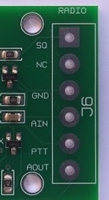
Top View, Right Side Of Module
Pin 1 has a square pad on pc board and all pads are labeled.
1) Squelch – The squelch line is active high and this can be inverted in software. Logic 1 when 3.3V/5V is applied. Logic 0 when 0 volts is applied. This line is current limited with a 100K resistor and should not load your circuit.
2) NC – No connection and is reserved.
3) GND – Common ground of radio.
4) AIN – This line is the mic input to your radio. The source of this line is from the Left/right channels, that passes first through a dc blocking capacitor, of your PC’s speaker audio. Its level can be adjusted by adjusting the speakers level on your PC to a level that does not overdrive your radio’s mic input.
5) PTT – This line is used to key your radio’s transceiver. It does this using a transistor to ground the PTT line. It can handle up to 200 mA. When not keyed, it is open circuit to your radio.
6) AOUT – This line is the receive audio output of your radio. The source of this line is from your radio, that passes first through a dc blocking capacitor, of your radio’s audio output. Its level can be adjusted by adjusting the microphone level on your PC to a level that does not overdrive your PC’s mic input.
LED Indicators
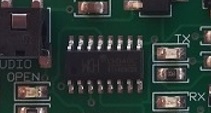
On the module there are three LED indicators. They are about in the center of the module. On the left above there is a blue LED labeled ‘OPEN’. This LED will turn on when a PC opens the USB COM port in software.
The second indicator is a red LED that goes on whenever the module turns on the PTT line or when your radio is transmitting. This is labeled ‘TX’. This is when the PTT line goes to ground.
The last indicator is a green LED that indicates the state of the squelch line. It is off when the squelch line is low and on when the squelch line is high. If the software has the detection inverted the opposite would be true. This is labeled ‘RX’.
PC Interfacing
The PC interface side is via a 3.5 mm 4 pole audio jack and a Micro B USB connector.
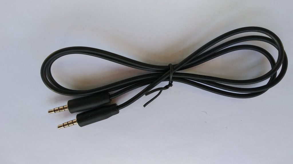
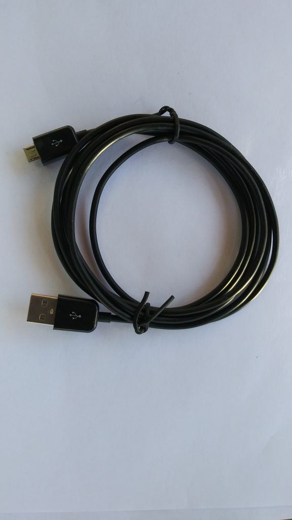
Above on the top is a suitable audio cable and above on the bottom is a suitable USB cable. Plug the audio cable into the interface module and the PC’s sound card. A 4 pole cable must be used. This cable carries both the mic and speaker audio. It is the convention being used on most newer PCs. If you have a separate mic and speaker inputs, a splitting adapter must be used.
References And Disclaimer
B9X Electronics
Website: https://b9xelectronics.com
B9X Voice Server™ and B9X Voice Client™ are trademarks of B9X Electronics.
Windows™ is a trademark of Microsoft Corporation.
Android™ and Google™ are trademarks of Google.
Yaesu™ and products mentioned are trademarks of Yaesu/Vertex Standard.
All other references are trademarks and copyrights of their respective
holders.
The specifications in this document are only given to provide information, without any guarantee in regards to either mistakes or omissions. B9X Electronics reserves the right to make changes to the products contained in this publication for any reason.
IN NO EVENT WILL B9X ELECTRONICS BE LIABLE TO YOU OR ANYONE FOR ANY DAMAGES, INCLUDING BUT NOT LIMITED TO INJURY TO PERSON OR PRODUCT, LOST PROFITS, LEGAL COSTS, LOST SAVINGS, OR OTHER INCIDENTAL OR CONSEQUENTIAL DAMAGES ARISING OUT OF THE USE OR INABILITY TO USE THIS AND ANY OF OUR PRODUCTS.